Main Valve
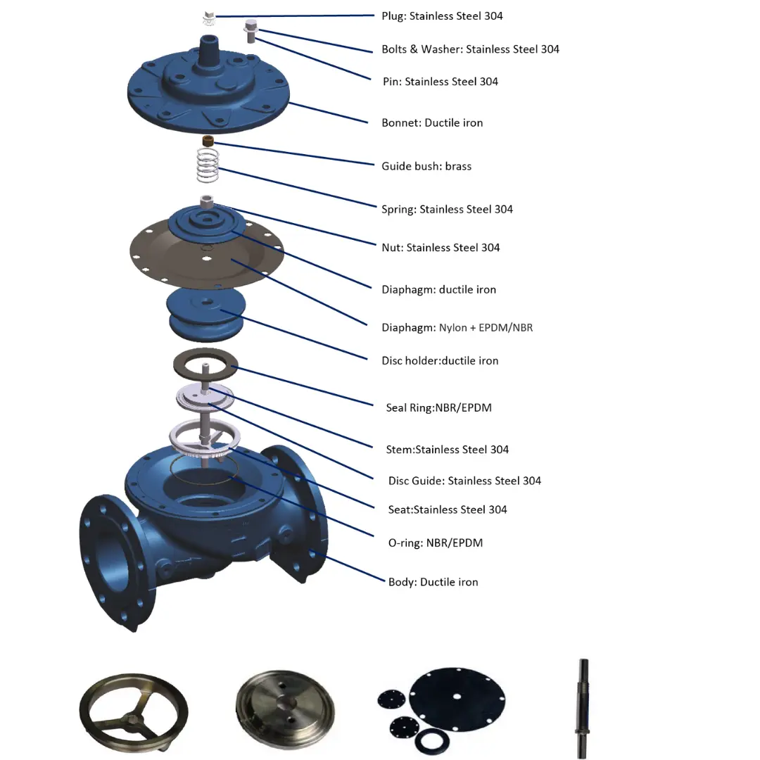
The AIP Main Valve DN400–800 is designed for efficient control and regulation of water flow in large pipeline systems. Manufactured with high-quality materials, it ensures durability, reliable performance, and long service life in municipal water supply, industrial, and infrastructure applications. Engineered for strength and precision, this valve provides stable pressure control and dependable operation in demanding pipeline networks. AIP Valves is also an IGBC member, supporting sustainable and eco-friendly infrastructure and building solutions.
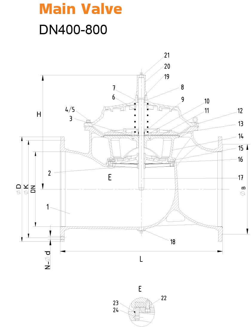
DN400-800
Component Breakdown
| No. | Description | Material | Standard |
|---|---|---|---|
| 1 | Body | Ductile Iron | GJS 500-7 |
| 2 | Seat | Stainless Steel | AISI 304/316 |
| 3 | Screw | Stainless Steel | A2/A4 |
| 4 | Screw | Stainless Steel | A2/A4 |
| 5 | Screw | Stainless Steel | A2/A4 |
| 6 | Spring | Stainless Steel | AISI 304/316 |
| 7 | Bonnet | Ductile Iron | GJS 500-7 |
| 8 | Bush | Brass | C61900 |
| 9 | O-ring | Rubber | NBR |
| 10 | Fix Washer | Brass | C61900 |
| 11 | Diaphragm | Nylon Reinforced Rubber | EPDM + Nylon Fabric |
| 12 | Eye Bolts | Carbon Steel | 1040 |
| 13 | Fixing Holder | Ductile Iron | GJS 500-7 |
| 14 | Disc Holder | Ductile Iron | GJS 500-7 |
| 15 | Seal | Rubber | EPDM |
| 16 | Seal Retainer | Ductile Iron | GJS 500-7 |
| 17 | Stem | Stainless Steel | AISI 304/316 |
| 18 | Plug | Stainless Steel | AISI 304/316 |
| 19 | O-ring | Rubber | NBR |
| 20 | Cap | Ductile Iron | GJS 500-7 |
| 21 | Plug | Stainless Steel | AISI 304/316 |
| 22 | Screw | Stainless Steel | A2/A4 |
| 23 | O-ring | Rubber | NBR |
| 24 | Screw | Stainless Steel | A2/A4 |
| DN | L | H | ØD (PN10) | ØD (PN16) | ØK (PN10) | ØK (PN16) | N-Ød (PN10) | N-Ød (PN16) | ØB (PN10) | ØB (PN16) |
|---|---|---|---|---|---|---|---|---|---|---|
| 400 | 1100 | 710 | 580 | 580 | 515 | 525 | 16-Ø28 | 16-Ø31 | 480 | 480 |
| *450 | 1200 | 720 | 640 | 640 | 585 | 585 | 20-Ø28 | 20-Ø31 | 530 | 548 |
| 500 | 1250 | 822 | 715 | 715 | 620 | 650 | 20-Ø28 | 20-Ø34 | 582 | 609 |
| 600 | 1450 | 885 | 840 | 840 | 725 | 770 | 20-Ø31 | 20-Ø37 | 682 | 720 |
| *700 | 1650 | 910 | 910 | 910 | 840 | 840 | 24-Ø31 | 24-Ø37 | 682 | 720 |
| 800 | 1850 | 1280 | 1025 | 1025 | 950 | 950 | 24-Ø34 | 24-Ø40 | 901 | 901 |
Key Notes:
DN: Nominal Diameter
L: Length | H: Height
ØD: Bolt Circle Diameter
ØK: Flange Diameter
N-Ød: Number of Bolt Holes & Bolt Hole Diameter (e.g.,
8-Ø19= 8 holes, Ø19 mm each).ØB: Bore Diameter
PN: Pressure Rating (PN10 = 10 bar, PN16 = 16 bar, PN25 = 25 bar).